


How does it work?
6DOF IMU 12 Click uses the BMI270, an ultra-low-power IMU optimized for wearable applications. The IMU combines precise acceleration and angular rate measurement with intelligent on-chip motion-triggered interrupt features. The 6-axis sensor combines a 16-bit triaxial gyroscope and a 16-bit triaxial accelerometer in a compact 2.5x3.0x0.8mm LGA package. BMI270 is a member of Bosch Sensortec’s BMI260 family of IMUs, targeting fast and accurate inertial sensing in wearable applications. It also features Bosch’s automotive-proven gyroscope technology with an improved accelerometer. Significant improvements in BMI270 include, but are not restricted to, the overall accelerometer performance, i.e. an extremely low zero-g offset and sensitivity error, low temperature drifts, robustness over PCB strain and a low noise density. It also features the industry’s first self-calibrating gyroscope using motionless CRT (Component Re-Trimming) functionality to compensate MEMS typical soldering drifts, ensuring post-soldering sensitivity errors down to ± 0.4%. BMI270 includes intuitive gesture, context and activity recognition with an integrated plug-and-play step counter/detector, which is optimized for accurate step counting in wrist-worn devices. The IMU is also well suited for other types of wearable devices, such as hearables, smart clothes, smart shoes, smart glasses and ankle bands.
The smart IMU has a wide range for VDD and VDDIO supply voltages. The performance and current consumption are stable over the entire supply range. Typical current draw for BMI270’s accelerometer and gyroscope at full ODR of 6.4 kHz is under 700μA. By enabling high output data rates with low current consumption, wearable manufacturers can avoid an unpleasant aliasing effect – an effect that causes different signals to become indistinguishable when sampled at lower ODRs. Bosch Sensortec’s ultra-low-power IMU BMI270 provides an intelligent power management system enabling motion-triggered always-on features to run inside the ultra-low-power domain of the IMU. BMI270 significantly extends system battery life by handling multiple activity tracking, step counting and gesture recognition functions independently of the main system processor, without having to wake it up. The processor-independent functions include tasks such as sending an interrupt when a certain number of steps is reached, or geofencing to activate GPS when the user stands up and starts walking.
The device features I2C and SPI serial interfaces, a VDD operating range from 1.71V to 3.6V, and a separate digital IO supply (VDDIO) from 1.2V to 3.6V. Communication with all registers of the device can be performed using either SPI at 10MHz or I2C at up to 1MHz.
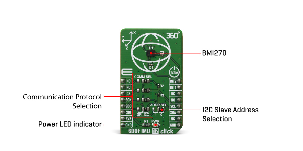
6DOF IMU 12 Click supports both SPI and I2C communication interfaces, allowing it to be used with a wide range of different MCUs. The communication interface can be selected by moving SMD jumpers grouped under the COM SEL to an appropriate position (SPI or I2C). The slave I2C address can also be configured by an SMD jumper when the Click board™ is operated in the I2C mode. An SMD jumper labeled as ADD SEL is used to set the least significant bit (LSB) of the I2C address.
Specifications
| Type | Acceleration,Gyroscope,Motion |
| Applications | An ideal choice for wearables, hearables, smart clothing, augmented / virtual reality. |
| On-board modules | 6DOF IMU 12 Click uses the BMI270 IC, a low power inertial measurement unit, from Bosch Sensortec. |
| Key Features | 16-bit triaxial gyroscope and a 16-bit triaxial accelerometer, ensuring post-soldering sensitivity errors down to ± 0.4%. |
| Interface | I2C,SPI |
| Compatibility | mikroBUS |
| Click board size | M (42.9 x 25.4 mm) |
| Input Voltage | 3.3V |
Pinout diagram
This table shows how the pinout on 6DOF IMU 12 Click corresponds to the pinout on the mikroBUS™ socket (the latter shown in the two middle columns).
| Notes | Pin | Pin | Notes | ||||
|---|---|---|---|---|---|---|---|
| NC | 1 | AN | PWM | 16 | INT2 | Interrupt 2 | |
| NC | 2 | RST | INT | 15 | INT1 | Interrupt 1 | |
| SPI Chip Select | CS | 3 | CS | RX | 14 | NC | |
| SPI Clock | SCK | 4 | SCK | TX | 13 | NC | |
| SPI Data OUT | SDO | 5 | MISO | SCL | 12 | SCL | I2C Clock |
| SPI Data IN | SDI | 6 | MOSI | SDA | 11 | SDA | I2C Data |
| Power Supply | 3.3V | 7 | 3.3V | 5V | 10 | NC | |
| Ground | GND | 8 | GND | GND | 9 | GND | Ground |
Onboard settings and indicators
| Label | Name | Default | Description |
|---|---|---|---|
| LD1 | PWR | - | Power LED Indicator |
| JP1 | ADDR SEL | Right | I2C Slave Address LSB selection: left position 1, right position 0 |
| JP2-5 | COMM SEL | Right | Communication interface selection: left position SPI, right position I2C |
Software Support
We provide a library for the 6DOF IMU 12 Click on our LibStock page, as well as a demo application (example), developed using MikroElektronika compilers. The demo can run on all the main MikroElektronika development boards.
Library Description
The library covers all the necessary functions to control 6DOF IMU 12 click board. Library performs a standard I2C and SPI interface communication.
Key functions:
uint8_t c6dofimu12_generic_read ( uint8_t reg )- Generic read the byte of data function.void c6dofimu12_burst_write ( uint8_t reg, uint8_t *p_tx_data, uint16_t n_len )- Generic sequential data write function.void c6dofimu12_get_data ( c6dofimu12_accel_t *accel_data, c6dofimu12_gyro_t *gyro_data )- Read Accel and Gyro data function.
Examples description
The application is composed of three sections :
- System Initialization - Initializes I2C and start to write log.
- Application Initialization - Initialization driver enables - I2C, check communication by read device ID, initializing the device, set default configuration for accelerometer and gyroscope, also write log.
- Application Task - (code snippet) This is an example which demonstrates the use of 6DOF IMU 12 Click board. Measured and display Accel and Gyro data coordinates values for X-axis, Y-axis and Z-axis. Results are being sent to the Usart Terminal where you can track their changes. All data logs write on USB uart changes for every 1 sec.
void application_task( ){ c6dofimu12_get_data ( &accel_data, &gyro_data ); mikrobus_logWrite( " Accel X :", _LOG_TEXT ); IntToStr( accel_data.x, log_text ); mikrobus_logWrite( log_text, _LOG_TEXT ); mikrobus_logWrite( " | ", _LOG_TEXT ); mikrobus_logWrite( " Gyro X :", _LOG_TEXT ); IntToStr( gyro_data.x, log_text ); mikrobus_logWrite( log_text, _LOG_LINE ); mikrobus_logWrite( " Accel Y :", _LOG_TEXT ); IntToStr( accel_data.y, log_text ); mikrobus_logWrite( log_text, _LOG_TEXT ); mikrobus_logWrite( " | ", _LOG_TEXT ); mikrobus_logWrite( " Gyro Y :", _LOG_TEXT ); IntToStr( gyro_data.y, log_text ); mikrobus_logWrite( log_text, _LOG_LINE ); mikrobus_logWrite( " Accel Z :", _LOG_TEXT ); IntToStr( accel_data.z, log_text ); mikrobus_logWrite( log_text, _LOG_TEXT ); mikrobus_logWrite( " | ", _LOG_TEXT ); mikrobus_logWrite( " Gyro Z :", _LOG_TEXT ); IntToStr( gyro_data.z, log_text ); mikrobus_logWrite( log_text, _LOG_LINE ); mikrobus_logWrite( "-------------------------------------", _LOG_LINE ); Delay_ms( 1000 );}The full application code, and ready to use projects can be found on our LibStock page.
Other mikroE Libraries used in the example:
- I2C or SPI
- UART
- Conversions
Additional notes and informations
Depending on the development board you are using, you may need USB UART click, USB UART 2 click or RS232 click to connect to your PC, for development systems with no UART to USB interface available on the board. The terminal available in all MikroElektronika compilers, or any other terminal application of your choice, can be used to read the message.
mikroSDK
This Click board™ is supported with mikroSDK - MikroElektronika Software Development Kit. To ensure proper operation of mikroSDK compliant Click board™ demo applications, mikroSDK should be downloaded from the LibStock and installed for the compiler you are using.
For more information about mikroSDK, visit the official page.
Shipping rates Australia wide and New Zealand
FAQ:
- How do I estimate shipping for my order?
- Add products in the shopping cart and head to the checkout page to estimate the shipping.
Dispatch time
Unless expressly agreed otherwise with you, we will not commence delivery of an order until we have received cleared payment of the purchase price in full.
All orders placed before 11 am AEST (Monday to Friday) will ordinarily be processed on the same day.
We will endeavour to ship the Products by the applicable time indicated on the website, but all times are indicative only. All shipping times are dispatch times only, and actual delivery dates will depend on the shipping method chosen, delivery address and delivery service provider.
Note- Please make a note during purchase if you require any item urgently. However we cannot guarantee that we will be able to comply with any request.
*Go to Australia post delivery time calculation to get various Australia post service in your area please use our shipping postcode Thomastown, 3074 as the "from" address - https://auspost.com.au/parcels-mail/delivery-times.html?ilink=tools-open-deliv-times.
We ship all products throughout mainland Australia, Tasmania and New Zealand - Including Darwin, Melbourne, Sydney, Tasmania, Adelaide, Brisbane, Perth, all metro and regional areas but do not deliver to areas in Australia where the Australia Post delivery network is not available.
Check Express shipping delivery coverage area at - http://auspost.com.au/parcels-mail/delivery-areas.html
Receipt of deliveries
Deliveries to post office boxes are not permitted where delivery is by courier. If delivery is by courier and nobody is available at the delivery address to accept delivery when delivery is attempted then the courier may either:
- leave the relevant parcel at the unattended address (the courier will do so if specified in your delivery requirements); or
- re-attempt delivery at a later time or date, in which case we may charge you an additional re-delivery fee.
Note that if a delivery is left unattended at the shipping address and is subsequently stolen then the theft is your responsibility, not ours.
Payment & Security
Your payment information is processed securely. We do not store credit card details nor have access to your credit card information.