


NOTE: Users also have an optimized version of this Click board™, the MCP251863 Click, where the controller and transceiver can be found in one package.
How does it work?
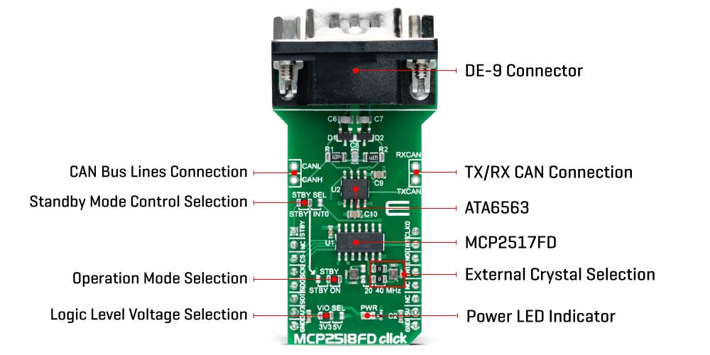
MCP2518FD Click as its foundation uses the MCP2518FD and ATA6563, an external CAN FD controller with an SPI interface and a high-speed CAN transceiver from Microchip. The ATA6563, a low-level physical layer IC (PHY), provides a physical connection with the CAN bus itself, while the CAN controller MCP2518FD represents an interface between the MCU and the PHY. The role of the CAN controller is to provide arbitration, message framing, message validation, error detection, message filtering, and more. Among all other tasks, it offers formatted CAN data for the application layer, running on the host MCU.
On the other side, the ATA6563, a high-speed CAN transceiver, provides a physical connection with the CAN bus. It allows communication speed up to 5Mbps and offers high resistance to electrostatic discharge and other electromagnetic phenomena. The ATA6563 supports Normal and Standby operational modes. Normal mode is engaged when the STBY pin, routed on the AN pin of the mikroBUS™ socket, is at the logic low level, while the TXD pin is held to a high logic level. While in the Normal mode, the data can be transmitted and received via the CAN H/L bus lines.
The mode selection can be made by positioning the SMD jumper labeled as STBY to an appropriate position marked as STBY or ON. In the case of Standby mode, if the STBY jumper is set to the STBY position, the user has the option of activating the Standby mode in two ways, where the selection is made by positioning the SMD jumper labeled as STBY SEL to an appropriate position marked as STBY or INT0. In this way, the Standby mode can be activated via STBY pin from the mikroBUS™ socket or by the MCP2518FD interrupt signal IN0 (the IN0 pin can also be used to alert the MCU about the TX events).
The MCP2518FD communicates with MCU using the SPI interface. In addition, the user can connect the external TX/RX signals to the CAN FD transceiver and CAN bus signals directly through the onboard headers on the right and left sides of the board. This Click board™ comes equipped with the standard DB-9 connector, making interfacing with the CAN bus simple and easy.
In addition, this Click board™ also uses several pins of the mikroBUS™ socket. The CLKO pin from the MCP2518FD routed to the PWM pin of the mikroBUS™ socket can be used to provide the clock output for the host MCU. It is derived from the input clock generated by the onboard chip oscillators, where the onboard SMD jumpers allow frequency selection between 20MHz and 40MHz. Besides, it also uses two interrupt pins, INT and INT1 routed to the INT and RX pins of the mikroBUS™ socket, respectively. While the INT pin is always an interrupt pin, used to alert the MCU of the enabled interrupt event, the INT1 pin alert the MCU about the RX events (if these interrupts are enabled).
This Click board™ can operate with both 3.3V and 5V logic voltage levels selected via the VIO SEL jumper. This way, it is allowed for both 3.3V and 5V capable MCUs to use the communication lines properly. However, the Click board™ comes equipped with a library containing easy-to-use functions and an example code that can be used, as a reference, for further development.
Specifications
Type CAN,CAN FD Applications Can be used for developing a wide range of automotive diagnostic applications, even on MCUs that do not natively support CAN interface On-board modules MCP2518FD - external CAN FD controller with an SPI interface from MicrochipATA6563 - high-speed CAN transceiver from Microchip Key Features Expands the existing MCU with the reliable and robust CAN connectivity option, support for both CAN 2.0B and CAN FD frames, high speed CAN communication up to 5 Mbps, integrated DE-9 connector, Interface GPIO,PWM,SPI Compatibility mikroBUS Click board size L (57.15 x 25.4 mm) Input Voltage 3.3V or 5V
Pinout diagram
This table shows how the pinout on MCP2518FD Click corresponds to the pinout on the mikroBUS™ socket (the latter shown in the two middle columns).
| Notes | Pin | Pin | Notes | ||||
|---|---|---|---|---|---|---|---|
| Standby Control | STBY | 1 | AN | PWM | 16 | CLKO | Clock Input |
| NC | 2 | RST | INT | 15 | INT | Interrupt | |
| SPI Chip Select | CS | 3 | CS | RX | 14 | IN0 | TX Interrupt |
| SPI Clock | SCK | 4 | SCK | TX | 13 | IN1 | RX Interrput |
| SPI Data OUT | SDO | 5 | MISO | SCL | 12 | NC | |
| SPI Data IN | SDI | 6 | MOSI | SDA | 11 | NC | |
| Power Supply | 3.3V | 7 | 3.3V | 5V | 10 | 5V | Power Supply |
| Ground | GND | 8 | GND | GND | 9 | GND | Ground |
Onboard settings and indicators
| Label | Name | Default | Description |
|---|---|---|---|
| LD1 | PWR | - | Power LED Indicator |
| JP1-JP2 | - | Right | External Crystal Selection 20MHz/40MHz: Left position 20MHz, Right position 40MHz |
| JP3 | VIO SEL | Left | Logic Level Voltage Selection 3V3/5V: Left position 3V3, Right position 5V |
| JP4 | STBY | Right | Operational Mode Selection STBY/ON: Left position STBY, Right position ON |
| JP5 | STBY SEL | Left | Standby Mode Control Selection STBY/INT0: Left position STBY, Right position INT0 |
| J1 | - | Unpopulated | External RXCAN/TXCAN Header |
| J2 | - | Unpopulated | External CANH/CANL Header |
MCP2518FD Click electrical specifications
| Description | Min | Typ | Max | Unit |
|---|---|---|---|---|
| Supply Voltage | 3.3 | - | 5 | V |
| Data Rate | - | - | 5 | Mbps |
| Operating Temperature Range | -40 | +25 | +120 | °C |
Software support
We provide a library for the MCP2518FD Click on our LibStock page, as well as a demo application (example), developed using MikroElektronika compilers. The demo can run on all the main MikroElektronika development boards.
Library Description
Library offers a choice to exchange messages with the other device by using CAN communication. Library also offers a choice to access a control, status and RAM registers of the device. For more details check documentation.
Key functions:
void MCP2518FD_transmitMessage( uint8_t numDataBytes, uint8_t *transmitFlag, uint8_t *dataIn )- Transmits the desired message and checks is message successfully sent.void MCP2518FD_receiveMessage( uint8_t *receiveFlag, uint8_t *dataOut )- Receives the message and checks is message successfully received.int8_t MCP2518FD_Configure(T_MCP2518FD_id index, T_MCP2518FD_cfg* config)- CAN Control register configuration.int8_t MCP2518FD_ConfigureObjectReset(T_MCP2518FD_cfg* config)- Reset Configure object to reset values.
Examples description
The application is composed of the three sections :
- System Initialization - Initializes peripherals and pins.
- Application Initialization - Initializes SPI interface and performs the device configuration to work properly.
- Application Task - (code snippet) - Always checks is new message in FIFO ready for receiving and when is message ready, receives a message from the other device. Also in this example we can sent the desired message via CAN communication to the other device. We can choose a message to be sent by sending the determined command to the UART. In this example the command, which determines a message, can be number from 1 to 7.
void applicationTask(){ if (UART_Rdy_Ptr()) { rxDat = UART_Rd_Ptr(); chPtr = &txd[0]; switch (rxDat) { case '1' : { _strcpy( chPtr, &txtMessage1[0] ); MCP2518FD_transmitMessage( 5, &checkFlag, &txd[0] ); if (checkFlag == 1) { mikrobus_logWrite( "Message Sent", _LOG_LINE ); } break; } case '2' : { _strcpy( chPtr, &txtMessage2[0] ); MCP2518FD_transmitMessage( 7, &checkFlag, &txd[0] ); if (checkFlag == 1) { mikrobus_logWrite( "Message Sent", _LOG_LINE ); } break; } case '3' : { _strcpy( chPtr, &txtMessage3[0] ); MCP2518FD_transmitMessage( 2, &checkFlag, &txd[0] ); if (checkFlag == 1) { mikrobus_logWrite( "Message Sent", _LOG_LINE ); } break; } case '4' : { _strcpy( chPtr, &txtMessage4[0] ); MCP2518FD_transmitMessage( 4, &checkFlag, &txd[0] ); if (checkFlag == 1) { mikrobus_logWrite( "Message Sent", _LOG_LINE ); } break; } case '5' : { _strcpy( chPtr, &txtMessage5[0] ); MCP2518FD_transmitMessage( 3, &checkFlag, &txd[0] ); if (checkFlag == 1) { mikrobus_logWrite( "Message Sent", _LOG_LINE ); } break; } case '6' : { _strcpy( chPtr, &txtMessage6[0] ); MCP2518FD_transmitMessage( 3, &checkFlag, &txd[0] ); if (checkFlag == 1) { mikrobus_logWrite( "Message Sent", _LOG_LINE ); } break; } case '7' : { _strcpy( chPtr, &txtMessage7[0] ); MCP2518FD_transmitMessage( 7, &checkFlag, &txd[0] ); if (checkFlag == 1) { mikrobus_logWrite( "Message Sent", _LOG_LINE ); } break; } default : { break; } } } MCP2518FD_receiveMessage( &checkFlag, &rxd[0] ); if (checkFlag == 1) { chPtr = &rxd[0]; mikrobus_logWrite( "Received Message : ", _LOG_TEXT ); mikrobus_logWrite( chPtr, _LOG_LINE ); }}Additional Functions :
- char * _strcpy( char * _to, char * _from ) - String copy function.
The full application code, and ready to use projects can be found on our LibStock page.
Other mikroE Libraries used in the example:
SPIUART
Additional notes and informations
Depending on the development board you are using, you may need USB UART click, USB UART 2 click or RS232 click to connect to your PC, for development systems with no UART to USB interface available on the board. The terminal available in all MikroElektronika compilers, or any other terminal application of your choice, can be used to read the message.
mikroSDK
This click board is supported with mikroSDK - MikroElektronika Software Development Kit. To ensure proper operation of mikroSDK compliant click board demo applications, mikroSDK should be downloaded from the LibStock and installed for the compiler you are using.
For more information about mikroSDK, visit the official page.
Shipping rates Australia wide and New Zealand
FAQ:
- How do I estimate shipping for my order?
- Add products in the shopping cart and head to the checkout page to estimate the shipping.
Dispatch time
Unless expressly agreed otherwise with you, we will not commence delivery of an order until we have received cleared payment of the purchase price in full.
All orders placed before 11 am AEST (Monday to Friday) will ordinarily be processed on the same day.
We will endeavour to ship the Products by the applicable time indicated on the website, but all times are indicative only. All shipping times are dispatch times only, and actual delivery dates will depend on the shipping method chosen, delivery address and delivery service provider.
Note- Please make a note during purchase if you require any item urgently. However we cannot guarantee that we will be able to comply with any request.
*Go to Australia post delivery time calculation to get various Australia post service in your area please use our shipping postcode Thomastown, 3074 as the "from" address - https://auspost.com.au/parcels-mail/delivery-times.html?ilink=tools-open-deliv-times.
We ship all products throughout mainland Australia, Tasmania and New Zealand - Including Darwin, Melbourne, Sydney, Tasmania, Adelaide, Brisbane, Perth, all metro and regional areas but do not deliver to areas in Australia where the Australia Post delivery network is not available.
Check Express shipping delivery coverage area at - http://auspost.com.au/parcels-mail/delivery-areas.html
Receipt of deliveries
Deliveries to post office boxes are not permitted where delivery is by courier. If delivery is by courier and nobody is available at the delivery address to accept delivery when delivery is attempted then the courier may either:
- leave the relevant parcel at the unattended address (the courier will do so if specified in your delivery requirements); or
- re-attempt delivery at a later time or date, in which case we may charge you an additional re-delivery fee.
Note that if a delivery is left unattended at the shipping address and is subsequently stolen then the theft is your responsibility, not ours.
Payment & Security
Your payment information is processed securely. We do not store credit card details nor have access to your credit card information.